|
Draw Polyline Button |
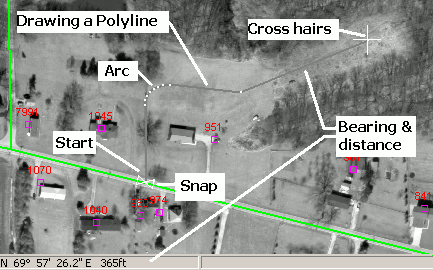
To draw a chain of lines (ie. polyline) on the map
1) Specify a Current Layer and Current Feature on the edit tool bar that this polyline entity will belong to. If necessary, first use the New Ftr button to create the feature to be drawn.
2) Click the ![]() button on the Editing Toolbar (or Ctrl-Shift-G).
button on the Editing Toolbar (or Ctrl-Shift-G).
3) Using the mouse, move the cross hairs to the location to start the polyline and press and release the left mouse button.
4) Next move the cross hairs to the end point, or next point, and click the left mouse button again.
5) Continue to trace the path by picking addition points as needed and then click the right mouse button (or Esc key) when finished.
6) While the cross hairs are still displayed, users can start drawing a second polyline representing this same feature (repeating steps 3-5) or click the right mouse button again to exit the drawing process.
Quick Reference:
Left Click Place vertex
Right Click Finished
Ctrl-Left Click Three point arc
Middle Click Update current feature.
D Type bearing and distance. see notes below
P Toggle on or off path mode. see notes below.
S Highlight vertexes
Ctrl-S Highlight vertexes and keep them on
Ctrl-Z Remove last vertex
Shift Hold down to disable snaps
Zooming:
Users can use any of the magnifying glass buttons to zoom in, zoom out, and pan while in the process of drawing. To do all drawing at a consistent viewing scale, use the Fixed Zoom button on the edit tool bar.
Bearing and Distance:
Many applications of drawing polylines involve simply tracing something already visible in the background aerial photography. Some applications, however, rely on survey data in the form of bearing and distance calls. There are a couple of different ways to use this type of information:
View bearing and distance readout as you draw: Move the cross hairs to place the next vertex, the message line in the lower left corner of the screen dynamically displays the bearing and distance of the line segment to be drawn. See example in picture above.
Type bearing and distance: To draw a line along a specified bearing distance first click on the starting point and then press the D key on the keyboard. Users can then enter the bearing and distance calls from a deed, for example, and the polyline will be drawn as the user types. See Bearing and Distance for instructions on using this window.
Path Mode:
Use path mode to simplify the process of tracing over already existing geometry such as when drawing a city boundary that follows a river. When in path mode, if both the starting and ending points of the segment being drawn are snapped to an existing vertex, then Think GIS checks to see if there is a an already existing path between the two points and if so it will highlight the path. If the highlighted path is the one desired, simply click the left mouse button as normal and several line segments are drawn to mimic the existing path. To not mimic the highlighted path, then either toggle path mode off (P key) or hold down the shift key to temporarily disable snapping.
Snaps:
Snaps are drawing aids that assist in lining up the polyline with existing points on the map. An example of this is the starting point of the polyline being drawn in the picture above. See Snaps for more information.
To insert an Arc :
1) After clicking the last vertex along the straight portion of the polyline (the point at the start of the arc), press and hold down the Ctrl key.
2) While holding down the Ctrl key click on a point about mid way along the desired arc path.
3) While still holding down the Ctrl key click on the ending point of the arc.
4) Release the Ctrl key to continue drawing normally. Think GIS does not have a true arc entity but instead draws the arc with several short line segments.
Notes:
•Users can also use the bearing and distance mode described above to draw arcs, or use the Circle button.
Other notes:
•Line style, width, and color are controlled using the Layer Settings window.
•Tool use instructions will also appear in the footer of the Think GIS window in the Instructional Bar.
|
Copyright © 2026 WTH Technology |