|
Draw Area Button |
An Area entity defines a region of the map contained within a defined boundary.
To draw an area on the map
1) Specify a Current Layer and Current Feature on the edit tool bar that this polyline entity will belong to. If necessary, first use the New Ftr button to create the feature to be drawn.
2) Click the ![]() button on the Editing Toolbar (or Ctrl-Shift-K).
button on the Editing Toolbar (or Ctrl-Shift-K).
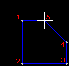
3) Using the mouse, move the cross hairs to the location to start the area boundary, and then press and release the left mouse button.
4) Next move the cross hairs to the next point along the border, and click the left mouse button again.
5) Continue to trace the perimeter of the area. Once the entire border is traced, click again on the starting point to finish, or click the right mouse button at any time and Think GIS will automatically close the area from the last point picked.
 6) While the cross hairs are still displayed, start drawing a second area representing this same feature (repeating steps 3-5) or click the right mouse button again to exit the drawing process.
Quick Reference:
Left Click Place vertex
Right Click Finished and auto-close
Ctrl-Left Click Three point arc
Middle Click Update current feature.
D Type bearing and distance. See note below.
P Toggle path mode on or off. See note below.
S Highlight vertexes
Ctrl-S Highlight vertexes and keep them on
Ctrl-Z Remove last vertex
Shift Hold down to disable snaps
Excluded areas (donuts)
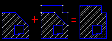
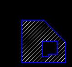 To indicate a hole in an area simply draw another area entity inside the first one. If the two entities belong to the same feature then they will be automatically combined into a single entity defining a region with a hole. Repeat this for drawing other holes in the same area.
Modifying an area
 The process of automatically combining intersecting areas has other functionality also. To extend a city limits area to include a newly annexed area, draw a new area entity adjacent to the existing one. If the two entities belong to the same feature and they share a common border (vertexes exactly match) then they will be automatically combined into one seamless area.
Overlapping areas
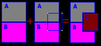 It is very common to have a layer made up of several different features where the areas representing each feature do not and should not overlap. For example zoning, zip codes, fire department boundaries, city limits, etc. To assist in maintaining this integrity, Think GIS will display a warning if the area entity being drawn overlaps with an existing area of another feature. At the same time, it also asks Think GIS to automatically remove the overlapping portion from the existing area(s). For example, zone A and zone B already exist on the map. It is decided to rezone a middle portion to zone C. To make this change on the map, simply draw a new area entity representing feature C in the correct place and Think GIS will automatically redraw zones A and B to exclude this new area.
Zooming:
Use any of the magnifying glass buttons to zoom in, zoom out, and pan while in the process of drawing. To do all your drawing at a consistent viewing scale, use the Fixed Zoom button on the edit tool bar.
Bearing and Distance:
Many applications of drawing areas involve simply tracing something already visible in the background aerial photography. Some applications, however, rely on survey data in the form of bearing and distance calls. There are a couple of different ways to use this type of information:
View bearing and distance readout as you draw: Move the cross hairs to place the next vertex, the message line in the lower left corner of the screen dynamically displays the bearing and distance of the line segment about to be drawn.
Type bearing and distance: To draw a line along a specified bearing distance first click on the starting point and then press the D key on the keyboard. Enter the bearing and distance calls from a deed for example, and the area boundary will be drawn as the user types. See Bearing and Distance for instructions on using this window.
Path Mode:
Use path mode to simplify the process of tracing over already existing geometry such as when drawing a city boundary that follows a river. When in path mode, if both the starting and ending points of the segment currently being drawn are snapped to an existing vertex, then Think GIS checks to see if there is already an existing path between the two points. If so, it will highlight the path. If the highlighted path is the one desired, click the left mouse button and several line segments are drawn to mimic the existing path. To not mimic the highlighted path, then either toggle path mode off (P key) or hold down the shift key to temporarily disable snapping.
Snaps:
Snaps are drawing aids that assist in lining up the polyline with existing points on the map. An example of this is the starting point of the polyline being drawn in the picture above. See Snaps for more information.
To insert an Arc :
1) After clicking the last vertex along the straight portion of the polyline (the point at the start of the arc), press and hold down the Ctrl key.
2) While holding down the Ctrl key click on a point about mid way along the desired arc path.
3) While still holding down the Ctrl key click on the ending point of the arc.
4) Release the Ctrl key to continue drawing normally. Think GIS does not have a true arc entity but instead draws the arc with several short line segments.
Notes:
•Users can also use the bearing and distance mode described above to draw arcs.
•The message line at the bottom of the screen displays the total area of the boundary drawn to that point. Also displayed is the bearing and distance of the line segment currently being drawn.
•See also Build Area tool for creating areas from existing lines on the map.
•The line color, and fill color of an area are controlled in Layer Settings.
•Tool use instructions will also appear in the footer of the Think GIS window in the Instructional Bar.
|
Copyright © 2026 WTH Technology |